AI Compute governance: Verifying AI chip location
post by Farhan · 2024-10-12T17:36:45.942Z · LW · GW · 0 commentsContents
  On-chip Mechanism for Location Verification
  Speed of light based verification
  Potential issues with this approach
  Let’s exercise?
    First Exercise
    Second exercise
    Third Exercise
  Proposal for solving the false positive issue. Ping and Cryptographic handshake based verification
  Potential issues with this approach
  Why not just use GPS?
  Feedback?
None
No comments
TL;DR: In this post I discuss a recently proposed on-chip compute governance mechanism, a delay based location verification mechanism. Then I demonstrate feasibility and applicability of the mechanism through a few exercises and identify a potential issue with frequent false positives. Finally I propose a potential solution for the identified issue.
Technical governance approaches will be critical for mitigating the risks posed by potentially misaligned AI systems. Even if the alignment problem is solved, technical governance methods will still likely be important for some time to limit misuse or the consequences of AI malfunctions.
Recent AI progress has largely been driven by increases in the amount of computing power used to train new models. Currently the compute used to train notable AI systems doubles every six months. Hence, governing compute could be an effective way to govern AI.

On-chip Mechanism for Location Verification
A subset of compute governance, “on-chip governance mechanisms” could allow a regulator to perform verification or impose restrictions. In this article we explore location verification mechanisms specifically, delay based verification.
Speed of light based verification
In a recent report CNAS (Centre for a New American Security) proposed a location verification mechanism that relies on the hard limit of the speed of light (300 km/ms) and the lower bound on latency from existing communications infrastructure(I believe the maximum available is 200km/ms for pure fiber optic).
This approach has the following main design parameters.
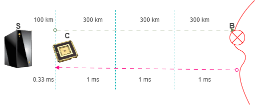
- The round trip distance (RTD) between subject chip and export control boundary (B) determines the maximum allowable round trip time (RTTmax), as calculated based on speed of light, for a verification handshake between the trusted server(S) and the subject chip(C).
- RTTmax = RTD(C–>B)/300
- Practical latency per distance (Lp) of communication infrastructure determines the maximum possible distance between trusted server and subject chip. The lowest bound on Lp is inverse of the speed of light in fibre optik (1ms/200km).
- RTDmax(S–>C) = RTTmax / Lp
- Substituting for RTTmax
- RTDmax(S–>C) = RTD(C–>B) / (Lp*300)
Potential issues with this approach
This approach relies on a very reliable universal constant (speed of light) to make assertions about the location of a chip. However, there are two complications that might make this approach difficult to implement.
- Need for trusted servers within every RTDmax(S–>C) radius of export sensitive AI chips. This might be prohibitive (although not impossible1), especially if the geographical location is prone to smuggling tendencies.
- Policy reliance on a inconsistent metric i.e. communication infrastructure latency might not be a reliable strategy. For instance, if there is congestion over the network, we might end up with considerable occurrences of false positives, as the RTTmax will expire occasionally.
- If a pure fiber connection can be ensured, we might be able to relax the distance constraint to 200KM/ms. ↩︎
- As measured on September 19th, 2024 ↩︎
Let’s exercise?
Let’s do a few exercises to see how the false positives issue might arise.
First Exercise
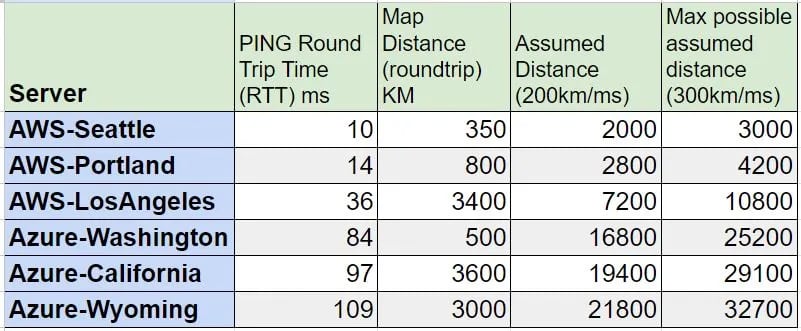
- Use AWS or Azure latency test to see the 3 minimum latency locations from where you are based. For me these are, Seattle, Portland and Los Angeles on AWS and Washington, California and Wyoming in Azure2.
- See if there are inconsistencies between both the sources (for me AWS is multi-folds faster than Azure).
- Populate a small table with the first two columns based on your location. The last two columns are calculated by formula i.e. 200*RTT and 300*RTT.
See how far the assumed distance would go? for me, the assumed distance for Azure easily goes across the Pacific.
Figure 4: Ping latencies for AWS and Azure from Fraser Valley in British Columbia, Canada, measured on September 19th, 2024. Second exercise
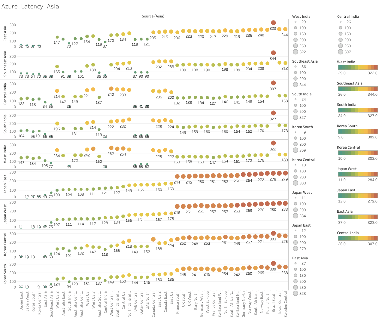
For the second exercise, we can use Azure region-region latency test data. The page shows monthly Percentile P50 round trip times (milliseconds) between Azure regions for a 30-day window. Below graphs are based on the 30-day period ending on June 19th, 2024 for the source region Asia.
Figure 5: monthly Percentile P50 round trip times (milliseconds) between Azure regions for a 30-day window
Follow the following steps;
- Choose any country from Asia, Europe or Africa (since borders are closer which makes the analysis fun).
- Find the minimum latency source-destination pair of your choosing.
- Calculate the estimated/assumed radius for this latency using the formulas for speed of light in vacuum and fiber optic.
- Use a mapping tool of your choice (like this one) that allows drawing circles and see what governance decisions would you take if you had to rely on the latency data to figure out the destination
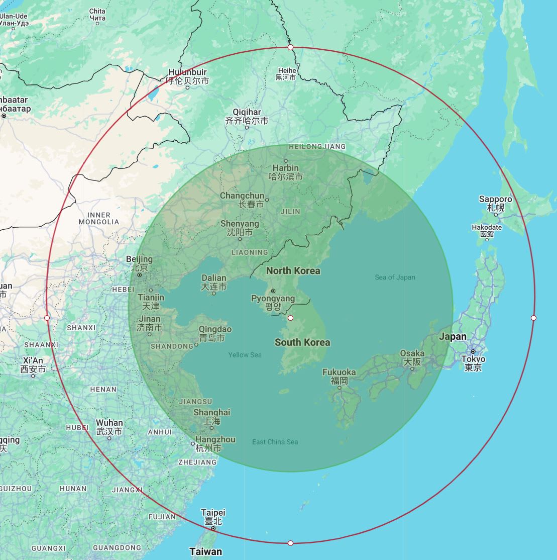
For this exercise, I chose the Azure datacenter pair of Korea Central and Korea South which incurs a latency of 10ms. for the estimated distances of 1000km (10/2*200) and 1500km (10/2*300), I get the following map.
Figure 6: Estimated distance from Seoul based on the latency between Central and Southern regions. Red circle is based on speed of light in vacuum. Green circle is based on speed of light in fiber.
Third Exercise
For your selected country, measure the distance to the border and determine the maximum bounds on latency allowed to avoid a false positive. For my chosen example, South Korea, A trusted server in Seoul is;
38km from the northern border with North Korea. This would necessitate a maximum round trip time (RTTmax) of 0.25ms (vacuum) or 0.38 ms(fibre)
390km from China over the Yellow sea. This would necessitate a maximum round trip time (RTTmax) of 2.6ms (vacuum) or 3.9 ms(fibre)
385km from China‘s border, after crossing N.Korea. This would necessitate a maximum round trip time (RTTmax) of 2.56ms (vacuum) or 3.85 ms(fibre)
500km to Japan over the sea of Japan. This would necessitate a maximum round trip time (RTTmax) of 3.3ms (vacuum) or 5ms(fibre)
It’s important to note though, that these distances are just estimated by point-to-point displacement on the map, and we might get longer distances if the communication infrastructure takes a longer route. Maybe a connectivity map of the locations might model it more accurately?
Proposal for solving the false positive issue. Ping and Cryptographic handshake based verification
Here I would like to propose an idea to augment the methodology introduced above, to overcome the false positive issue. The false positive issue would arise because of network congestion, which is a dynamic value which could fluctuate within a certain QoS bounds, based on the traffic on the network, at the time a verification query is issued. Adding this component to the formula for verification, as a static parameter is the cause of inaccuracies. To overcome this, this technique makes the following observations;
When performing a cryptographic handshake to verify location, we measure two components of latency. First, the latency from our trusted source to the subject chip’s reported location (a known location), and second, the latency for the actual cryptographic handshake.
The first component of latency for the reported location, can be measured independently using usual ping mechanisms, without having to verify the identity of the chip.
The second component of latency, cryptographic signature, is likely very small (< 1ms) or constant irrespective of the location of the subject chip.
The difference between a usual ping latency and cryptographic handshake query could give us valuable information while canceling out the network congestion component from S to reported location while preserving any network latency if the true location of C is different than reported location.
The mechanism works as follows;
Trusted server S issues a ping to known IP of chip C, getting RTTp.
Trusted server S issues cryptographic handshake query to chip C, getting RTTh.
Handshake Overhead is calculated as HO = RTTh – RTTp
Handshake Overhead is compared with Handshake Overhead Golden (calculated in-house), to get Latency between Chip’s reported location and Chip’s true location as L(Cr –>Ct) = HO – HOgld .
L(Cr –>Ct) is monitored throughout the life of the chip and alarms are raised when anomalies are detected.
Assertions about chip’s true location can still be made by using L(Cr –>Ct) instead of L(S–>C) for the formulas based on speed of light.
I believe, this approach would still work if the cryptographic handshake is supposed to be initiated by C.
Potential issues with this approach
There are a few potential ways this approach could be exploited;
Poisoning of latency baseline data, where a latency overhead is engineered into any ping query to mask any future L(Cr –>Ct). However a baseline for network latency can be established by querying other IPs on the same network or nearby geographic locations.
Some clever rerouting of cryptographic handshake query to subject IP. However, this would effect any verification mechanism.
Modifying packet contents for Ping or Handshake queries
This approach would not work where IP of machine using the subject chip is not reported. Moreover, I would also like to highlight that manipulation of delay-based internet geolocation by adversaries has been demonstrated to be possible, for example in the work by Abdou et.al. For this Article, I assume that countermeasures have been taken to mitigate such adversarial attacks.
Why not just use GPS?
When location and chips are mentioned in the same breath, one naturally expects to see GPS mentioned. So it begs the question why GPS is not being considered as a possible solution? However privacy regulations would not allow a GPS based solution, GPS is an unencrypted and insecure protocol that can be trivially spoofed, and GPS signals might be obstructed in data center facilities.
Feedback?
Feel free to comment or reach out for any feedback or suggestions on this. This is still only a proposal and I still have to
0 comments
Comments sorted by top scores.