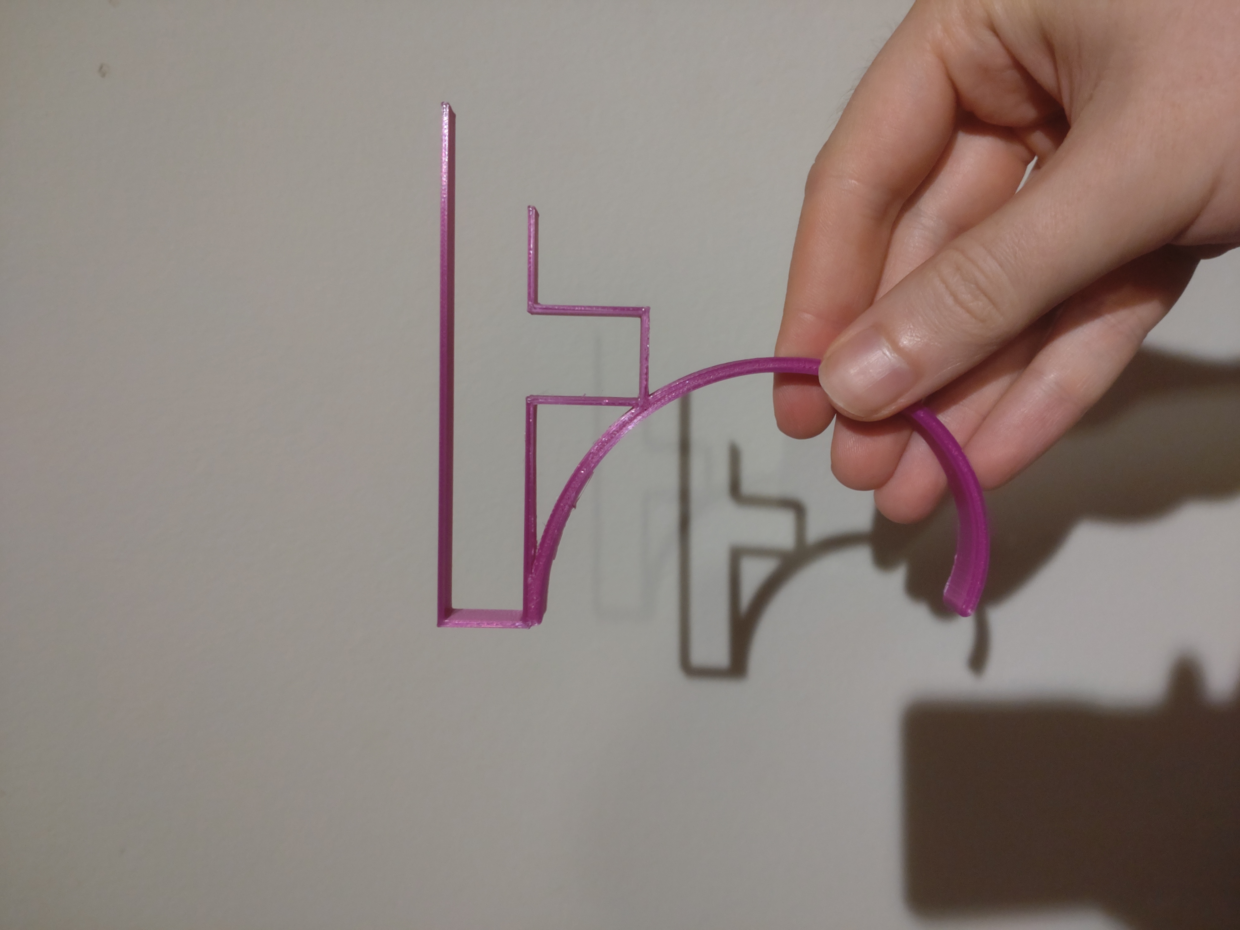
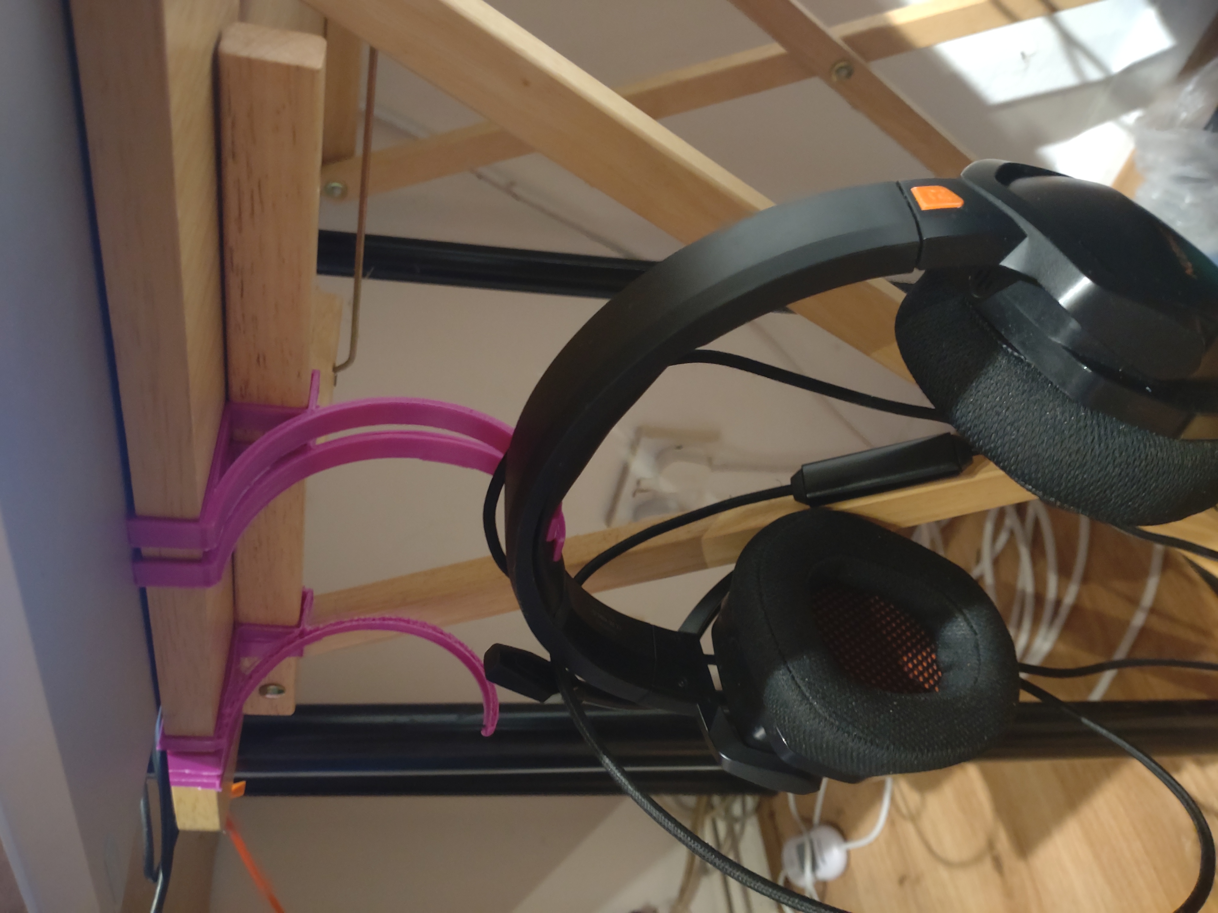
Headphones hook
post by philh · 2023-09-29T22:50:04.962Z · LW · GW · 1 commentsContents
1 comment
Some months ago I got a 3D printer. (An Anycubic Kobra Go, which was pretty high up the list of "best value for money for a starter printer" that I found through /r/3Dprinting at the time.) I haven't used it much, but recently I used it to solve an itch. I wanted my headphones to be in easy reach, so I designed and printed a hook that I could slide over the edge of the table near my desk. This is the first thing I've designed and I'm pretty happy with how it came out!
The curve was pretty awkward. I was working with OpenSCAD (maybe something else would have been easier?) which doesn't have an easy way that I found to draw nice curves. (Lines in general seem annoying, you can extrude a 2d shape to 3d but not a 1d shape to 2d?)
I decided to go with an Archimedean spiral, and did a bunch of math to figure out how the various parameters had to relate to each other.1 I ended up with equations that I'd have had to solve numerically because they probably had no closed form. Then rather than writing a simple script to give me the answers I just eyeballed it, figuring I could redo it properly if I felt like it. Seems basically fine though.
I ended up printing three copies. The first had a nozzle jam about half way through so it came out shitty. You can see it in the background of the second pic. It actually works, but it doesn't have enough friction on the table so it sags down. I can use it for looping cable over, though a deeper hook would be better at that. The second was mostly fine, but I decided I wanted 100% infill on the curve for strength and for some reason I did that by making the walls thick. In hindsight that's silly, it's pretty flexible and when you bend it a bit it starts to split along the middle. So I did one with normal walls and normal 100% infill and it's absolutely fine. These two are the ones actually holding it up in the second picture, I might print a third to get less pressure on the padding.
I could have made something simpler if I wanted to fasten it to the table, either with screws or duct tape. But I like that it doesn't need that.
The exact design probably won't be any use to anyone who doesn't have the same model of cheap folding table as me. But in case it's interesting or helpful, here's the .scad:
.scad file
top_depth = 1.5;
bottom_depth = 1.5;
vert_depth = 1.5;
hook_depth = 3;
width = 10;

top_length = 100;
edge_height = 15.54;
b1_length = 45;
support_height = 22.4;
b2_length = 16.3;
b3_length = 20;
hook_drop = 30;

rotate([90, 0, 0]) {

color("red")
  cube([top_length + vert_depth, width, top_depth]);

color("yellow")
  translate([top_length, 0, -edge_height])
  cube([vert_depth, width, edge_height]);

color("red")
  translate([top_length - b1_length, 0, -edge_height - bottom_depth])
  cube([b1_length + vert_depth, width, bottom_depth]);

color("yellow")
  translate([top_length - b1_length, 0, -edge_height - support_height])
  cube([vert_depth, width, support_height - bottom_depth]);

color("red")
  translate([top_length - b1_length - b2_length - vert_depth,
             0,
             -edge_height - support_height - bottom_depth])
  cube([b2_length + 2*vert_depth, width, bottom_depth]);

color("yellow")
  translate([top_length - b1_length - b2_length - vert_depth,
             0,
             -edge_height - support_height])
  cube([vert_depth, width, support_height - bottom_depth]);

color("red")
  translate([top_length - b1_length - b2_length - b3_length,
             0,
             -edge_height - bottom_depth])
  cube([b3_length, width, bottom_depth]);

color("green")
  translate([top_length + vert_depth,
             width,
             -edge_height - bottom_depth])
  rotate([90, 0, 0])
  scale([-1, 1, 1])
  linear_extrude(width)
  archimedean([+10,-58], 43, 0.15, -98, 98, width=3, $fn=180);
}

// https://openhome.cc/eGossip/OpenSCAD/ArchimedeanSpiral.html
module line(point1, point2, width = 1, cap_round_1 = true, cap_round_2 = true) {
    angle = 90 - atan((point2[1] - point1[1]) / (point2[0] - point1[0]));
    offset_x = 0.5 * width * cos(angle);
    offset_y = 0.5 * width * sin(angle);

    offset_1 = [offset_x, -offset_y];
    offset_2 = [-offset_x, offset_y];

    if (cap_round_1)
        translate(point1) circle(d = width, $fn = 24);
    if (cap_round_2)
        translate(point2) circle(d = width, $fn = 24);

    polygon(points=[
        point1 + offset_1, point2 + offset_1,
        point2 + offset_2, point1 + offset_2
    ]);
}

module polyline(points,
                width = 1,
                cap_round_1 = true,
                cap_round_2 = true)
{
    module polyline_inner(points, index) {
        if(index < len(points)) {
            line(points[index - 1], points[index], width,
            cap_round_1 = index > 1 || cap_round_1,
            cap_round_2 = index < len(points) - 1 || cap_round_2);
            polyline_inner(points, index + 1);
        }
    }

    polyline_inner(points, 1);
}

module archimedean(center, a, b, theta_1, theta_2, width=1, $fn=24) {
    d_theta = (theta_2 - theta_1)/$fn;
    thetas = [ for (i = [0:$fn]) theta_1 + i * d_theta ];
    points = [ for (t = thetas) center + [(a + b * t)*cos(t), (a + b*t)*sin(t)] ];
    polyline(points, width=width);
}
-
There are six parameters: x and y position of the center, initial and final radius, and the angular section to draw. There are two points I wanted the curve to pass through, plus I wanted it to be tangent to the horizontal at the first point, and I wanted the start and end points of the curve to be vertically above each other. It turns out that leaves one degree of freedom, letting me choose a smaller curve with more upswing at the end or a larger one with less. I went with a spiral that would have 5.4 cm between each turn, if it had multiple turns. ↩
1 comments
Comments sorted by top scores.

